Portable PIM Testers
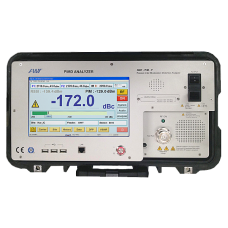
AWT’s Portable PIM testers are powerful yet compact tools for testing and analyzing telecommunications network infrastructure. These testers are ruggedized and can withstand harsh environmental conditions and are accurate, reliable and very easy to operate; furthermore, they provide a wealth of features ideal for work in the field.
Data Sheet Promotional Video Sales Offices eContact us Financing
Features
Multiple Test Modes: Field Diagnostic, Analyzer, Multi PIM, PIM over time, Rx Sweep Mode, Distance to PIM, VSWR, Distance to Fault, Single Carrier. First PIM Testers with embedded Distance to PIM (DTP) and Distance to Fault (VSWR) capability.
- Measures Intermodulation products IM3, IM5 IM7, IM9, IM11 and IM13.
- Very high PIM sensitivity: -172 dBc @ 2x 43 dBm carriers.
- Output power variable from 15dBm to 44dBm. Ideal for in-building DAS installations.
- Single Carrier Mode for system insertion loss measurements.
- PIM vs. Time Graph, Min-Maxhold feature. Perfect for static and dynamic PIM measurements.
- True constant power carriers – fully compliant to PIM standard IEC62037.
- Removable Case Lid
Leading Global wireless carriers use PIM analyzers to improve the quality of their networks. Low PIM installations are particularly important when wireless networks operate close to full cell capacity. Signal degradation affects revenue streams directly due to reduced data capacity.
Field use demands ruggedized yet accurate, test instruments. Our portable PIM testers are designed for this environment and an withstand tough conditions. An embedded module for accurate Distance to Fault (VSWR) and Distance to PIM measurements is available as option. Patented technology, provides very accurate indication of PIM sources.
Passive Intermodulation – PIM
Passive Intermodulation (PIM) is an unwanted mixing effect caused by non-linearity of passive components in the RF path of telecommunication systems. PIM diverts signal energy to other frequencies (spurious signals). This can generate interfering signals that may fall into receiving bands causing serious degradation of system performance.
Causes of PIM
- Dissimilar metals with different electrical properties as well as corroded components and structures.
- Ferromagnetic metals like iron, nickel and steel, show hysteresis effects when RF energy is applied.
- Irregular contact areas, even on a microscopic scale, cause an inconsistent flow of electrons, generating inhomogeneous electrical fields.
- Spark discharges that may happen by accidental “hot” connections and disconnections create craters on the connectors’ surfaces and lead to chemical reactions
RF Components that may cause PIM
- Cables
- Connectors
- Antennas
- Attenuators, Loads
- Surge Protectors
- Filters, Diplexers, Duplexers
- Combiners, Splitters, Couplers
Model |
Description |
Tx Frequency (MHz) |
Rx Frequency (MHz) |
| PP700U | LTE700-U | 730 ~ 759 | 776 ~ 788 |
| PP700L | LTE700-L | 728 ~ 759 | 698 ~ 716 |
| PP700APT | APT700 / Asia Pacific Telecommunity / 3GPP-28 | 758 ~ 803 | 703 ~ 748 |
| PP800 | LTE800 | 791 ~ 821 | 832 ~ 862 |
| PP850 | AMPS/CDMA | 869 ~ 896 | 824 ~ 851 |
| PP900 | GSM900 | 935 ~ 960 | 890 ~ 915 |
| PP900E | EGSM900 | 925 ~ 960 | 880 ~ 915 |
| PP1500JP | LTE-JP1500 | 1488 ~ 1520 | 1456 ~ 1480 |
| PP1800 | DCS/GSM1800 | 1805 ~ 1880 | 1710 ~ 1785 |
| PP1900 | PCS1900 | 1930 ~ 1990 | 1850 ~ 1910 |
| PP1921PA | PCS1900 & 2100AWS | 1930 ~ 1935 2110 ~ 2155 |
1850 ~ 1910 1710 ~ 1755 |
| PP2100AWS | AWS | 2010 ~ 2155 | 1710 ~ 1755 |
| PP2000TD | TD-SCDMA(2000) | 2010 ~ 2025 | 1900 ~ 1920 |
| PP2100UMTS | UMTS/W-CDMA | 2110 ~ 2170 | 1920 ~ 1980 |
| PP2160JP | W-CDMA-JP | 2150 ~ 2170 | 2110 ~ 2140 |
| PP2400LTE | LTE2400, Band 40 | 2355 ~ 2400 | 2300 ~ 2345 |
| PP2500 | Band 41, BRS / EBS | 2593 ~ 2690 | 2496 ~ 2580 |
| PP2600LTE | IMT-E(2600) | 2620 ~ 2690 | 2500 ~ 2570 |
| PPWBKR | WiBro-KR | 2110 ~ 2170 2300 ~ 2390 |
1910 ~ 1990 |
Accessories |
|||
| PPOPT1 | Distance-to-PIM(DTP), VSWR, Distance-to-Fault Option embedded in tester. | ||
| PACC2 | Accessory Kit: low PIM cables 3m / 10ft, low PIM load 50W / 10W DIN(m)-DIN(f), 690-2800 MHz, PIM <-165dBc @ 2x43dBm, (4) adapters, torque wrench, hard carry case IP66 | ||
| PIMGEN | PIM Source: Generator with preset PIM value -80dBm (+/- 10). Quick indication of system functionality. Ideal for test and training. | ||
| PLOAD100 | Low PIM load 100W, PIM < -165 dBc, 690-2800 MHz, with handle. | ||
| PLOAD50 | Low PIM load 50W / 10W (25 mins / permanent), PIM < -165 dBc, 690 – 2800 MHz, dual port DIN(m)-DIN(f), with ear for carabiner or strap. | ||
| LIC308DMDM-2M | Low PIM cable 2m (6ft), PIM < -165dBc @ 2×43 dBm, DIN(m)-DIN(m). | ||
| LIC308DMDM-3M | Low PIM cable 3m (10ft), PIM < -165dBc @ 2×43 dBm, DIN(m)-DIN(m). | ||
| ADA-DMDF | Connector Saver. Adapter DIN(m)-DIN(f), PIM <-165dBc @ 2×43 dBm. Protects Measurement port of PIM analyzers and loads. | ||
Specifications
Transmitter |
|
| Carrier Power | +15 to +44 dBm (46 dBm optional) |
| Power Accuracy | +/- 0.35 dB |
| Frequency Accuracy | 2 ppm |
| Reverse Pwr. Protection | +43 dBm for 5 sec |
Receiver |
|
| Reverse IM @ 2x43dBm PP1921PA |
-129 dBm / -172 dBc typ. -125 dBm / -168 dBc typ. |
| Noise Floor ( BW: 300 HZ / 1200 Hz) | – 138 dBm/ -132 dBm |
| DynamicRange(typical) | > 96 dB (ref: -70 dBm) |
| Reverse Power Protection | +43 dBm for 5 sec |
| Operational Input Power | -45 dBm RMS |
| Max Input Power | 0 dBm |
| Measurement Accuracy | +/- 1.0 dB @ 2 x 43 dBm |
Distance to PIM / Distance to VSWR (Option) |
|
| DTP Accuracy | 0.5 m typ. |
| DTF Accuracy (VSWR) | 0.5 m |
| Cable Types | Built-in list of cables Editing and adding new cable types |
Dimensions / Weight / Environment / Electrical |
|
| Dimensions | 457 x 305 x 500 (mm) 18.0 x 12.0 x 19.7 (inch) |
| Weight (frequency > 1 GHz) | 27 kg (26 kg) |
| Temperature | -10 °C to +50 °C |
| Humidity | 90%, RH (non condensing) |
| Protection | IP66 / IP20 |
| AC Power | 100 to 240V 50/60 Hz |
| Power Consumption | 640 Watts (VA) |


